Appearance
串口设备
访问的时候使用到的函数
| 函数 | 描述 |
|---|---|
| rt_device_find() | 查找设备 |
| rt_device_open() | 打开设备 |
| rt_device_read() | 读取数据 |
| rt_device_write() | 写入数据 |
| rt_device_control() | 控制设备 |
| rt_device_set_rx_indicate() | 设置接收回调函数 |
| rt_device_set_tx_complete() | 设置发送完成回调函数 |
| rt_device_close() | 关闭设备 |
查找
c
rt_device_t rt_device_find(const char* name);一般情况下,注册到系统的串口设备名称为 uart0,uart1等,使用示例如下所示:
c
#define SAMPLE_UART_NAME       "uart2"    /* 串口设备名称 */
static rt_device_t serial;                /* 串口设备句柄 */
/* 查找串口设备 */
serial = rt_device_find(SAMPLE_UART_NAME);
打开一个串口设备
c
rt_err_t rt_device_open(rt_device_t dev, rt_uint16_t oflags);c#define RT_DEVICE_FLAG_STREAM 0x040 /* 流模式 */ /* 接收模式参数 */ #define RT_DEVICE_FLAG_INT_RX 0x100 /* 中断接收模式 */ #define RT_DEVICE_FLAG_DMA_RX 0x200 /* DMA 接收模式 */ /* 发送模式参数 */ #define RT_DEVICE_FLAG_INT_TX 0x400 /* 中断发送模式 */ #define RT_DEVICE_FLAG_DMA_TX 0x800 /* DMA 发送模式 */串口数据接收和发送数据的模式分为 3 种:中断模式、轮询模式、DMA 模式。
默认使用轮询模式。
RT_DEVICE_FLAG_STREAM:流模式用于向串口终端输出字符串:当输出的字符是
"\n"(对应 16 进制值为 0x0A)时,自动在前面输出一个"\r"(对应 16 进制值为 0x0D) 做分行。
c
#define SAMPLE_UART_NAME       "uart2"    /* 串口设备名称 */
static rt_device_t serial;                /* 串口设备句柄 */
/* 查找串口设备 */
serial = rt_device_find(SAMPLE_UART_NAME);

/* 以中断接收及轮询发送模式打开串口设备 */
rt_device_open(serial, RT_DEVICE_FLAG_INT_RX);
控制
c
rt_err_t rt_device_control(rt_device_t dev, rt_uint8_t cmd, void* arg);
dev 设备句柄 cmd 命令控制字,可取值:RT_DEVICE_CTRL_CONFIG arg 控制的参数,可取类型: struct serial_configure 返回 RT_EOK函数执行成功, RT_ENOSYS执行失败,dev 为空
c
struct serial_configure
{
    rt_uint32_t baud_rate;            /* 波特率 */
    rt_uint32_t data_bits    :4;      /* 数据位 */
    rt_uint32_t stop_bits    :2;      /* 停止位 */
    rt_uint32_t parity       :2;      /* 奇偶校验位 */
    rt_uint32_t bit_order    :1;      /* 高位在前或者低位在前 */
    rt_uint32_t invert       :1;      /* 模式 */
    rt_uint32_t bufsz        :16;     /* 接收数据缓冲区大小 */
    rt_uint32_t reserved     :4;      /* 保留位 */
};c/* 波特率可取值 */ #define BAUD_RATE_2400 2400 #define BAUD_RATE_4800 4800 #define BAUD_RATE_9600 9600 #define BAUD_RATE_19200 19200 #define BAUD_RATE_38400 38400 #define BAUD_RATE_57600 57600 #define BAUD_RATE_115200 115200 #define BAUD_RATE_230400 230400 #define BAUD_RATE_460800 460800 #define BAUD_RATE_921600 921600 #define BAUD_RATE_2000000 2000000 #define BAUD_RATE_3000000 3000000 /* 数据位可取值 */ #define DATA_BITS_5 5 #define DATA_BITS_6 6 #define DATA_BITS_7 7 #define DATA_BITS_8 8 #define DATA_BITS_9 9 /* 停止位可取值 */ #define STOP_BITS_1 0 #define STOP_BITS_2 1 #define STOP_BITS_3 2 #define STOP_BITS_4 3 /* 极性位可取值 */ #define PARITY_NONE 0 #define PARITY_ODD 1 #define PARITY_EVEN 2 /* 高低位顺序可取值 */ #define BIT_ORDER_LSB 0 #define BIT_ORDER_MSB 1 /* 模式可取值 */ #define NRZ_NORMAL 0 /* normal mode */ #define NRZ_INVERTED 1 /* inverted mode */ /* 接收数据缓冲区默认大小 */ #define RT_SERIAL_RB_BUFSZ 64接收缓冲区:当串口使用中断接收模式打开时,串口驱动框架会根据 RT_SERIAL_RB_BUFSZ 大小开辟一块缓冲区用于保存接收到的数据,底层驱动接收到一个数据,都会在中断服务程序里面将数据放入缓冲区。
RT-Thread 提供的默认串口配置如下,即 RT-Thread 系统中默认每个串口设备都使用如下配置:
c
#define RT_SERIAL_CONFIG_DEFAULT           \
{                                          \
    BAUD_RATE_115200, /* 115200 bits/s */  \
    DATA_BITS_8,      /* 8 databits */     \
    STOP_BITS_1,      /* 1 stopbit */      \
    PARITY_NONE,      /* No parity  */     \
    BIT_ORDER_LSB,    /* LSB first sent */ \
    NRZ_NORMAL,       /* Normal mode */    \
    RT_SERIAL_RB_BUFSZ, /* Buffer size */  \
    0                                      \
}
在修改缓冲区大小时请注意,缓冲区大小无法动态改变,只有在 open 设备之前可以配置。open 设备之后,缓冲区大小不可再进行更改。但除缓冲区之外的其他参数,在 open 设备前 / 后,均可进行更改。
发送数据
c
rt_size_t rt_device_write(rt_device_t dev, rt_off_t pos, const void* buffer, rt_size_t size);
参数 描述 dev 设备句柄 pos 写入数据偏移量,此参数串口设备未使用 buffer 内存缓冲区指针,放置要写入的数据 size 写入数据的大小 返回 写入数据的实际大小, 0需要读取当前线程的 errno 来判断错误状态
发送的回调函数
c
rt_err_t rt_device_set_tx_complete(rt_device_t dev, rt_err_t (*tx_done)(rt_device_t dev,void *buffer));回调函数由调用者提供,当硬件设备发送完数据时,由设备驱动程序回调这个函数并把发送完成的数据块地址 buffer 作为参数传递给上层应用。
接收回调函数
c
rt_err_t rt_device_set_rx_indicate(rt_device_t dev, rt_err_t (*rx_ind)(rt_device_t dev,rt_size_t size));若串口以中断接收模式打开,当串口接收到一个数据产生中断时,就会调用回调函数,并且会把此时缓冲区的数据大小放在 size 参数里,把串口设备句柄放在 dev 参数里供调用者获取。
串口以 DMA 接收模式打开,当 DMA 完成一批数据的接收后会调用此回调函数。
接收数据
c
rt_size_t rt_device_read(rt_device_t dev, rt_off_t pos, void* buffer, rt_size_t size);| 参数 | 描述 |
|---|---|
| dev | 设备句柄 |
| pos | 读取数据偏移量,此参数串口设备未使用 |
| buffer | 缓冲区指针,读取的数据将会被保存在缓冲区中 |
| size | 读取数据的大小 |
| 返回 | 读到数据的实际大小, 0: 需要读取当前线程的 errno 来判断错误状态 |
cstatic rt_device_t serial; /* 串口设备句柄 */ static struct rt_semaphore rx_sem; /* 用于接收消息的信号量 */ /* 接收数据的线程 */ static void serial_thread_entry(void *parameter) { char ch; while (1) { /* 从串口读取一个字节的数据,没有读取到则等待接收信号量 */ while (rt_device_read(serial, -1, &ch, 1) != 1) { /* 阻塞等待接收信号量,等到信号量后再次读取数据 */ rt_sem_take(&rx_sem, RT_WAITING_FOREVER); } /* 读取到的数据通过串口错位输出 */ ch = ch + 1; rt_device_write(serial, 0, &ch, 1); } }
关闭
c
rt_err_t rt_device_close(rt_device_t dev);实际使用
使用中断的模式
- 在board.h文件里面
c
/*-------------------------- UART CONFIG BEGIN --------------------------*/
/** After configuring corresponding UART or UART DMA, you can use it.
*
* STEP 1, define macro define related to the serial port opening based on the serial port number
* such as #define BSP_USING_UART1
*
* STEP 2, according to the corresponding pin of serial port, define the related serial port information macro
* such as #define BSP_UART1_TX_PIN "PA9"
* #define BSP_UART1_RX_PIN "PA10"
*
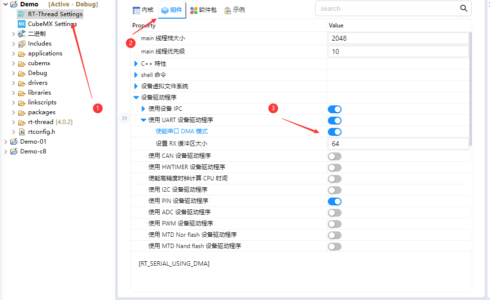
* STEP 3, if you want using SERIAL DMA, you must open it in the RT-Thread Settings.
* RT-Thread Setting -> Components -> Device Drivers -> Serial Device Drivers -> Enable Serial DMA Mode
*
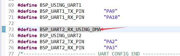
* STEP 4, according to serial port number to define serial port tx/rx DMA function in the board.h file
* such as #define BSP_UART1_RX_USING_DMA
*
*/
#define BSP_USING_UART1
#define BSP_UART1_TX_PIN "PA9"
#define BSP_UART1_RX_PIN "PA10"
#define BSP_USING_UART2
#define BSP_UART1_TX_PIN "PA2"
#define BSP_UART1_RX_PIN "PA3"
这个是老师的失误, 不需要, 需要的头文件rt_device.h
c
#include <rtthread.h>
#define DBG_TAG "main"
#define DBG_LVL DBG_LOG
#include <rtdbg.h>
#include <rtdevice.h>
rt_device_t u2_dev;
rt_sem_t u2_sem;
rt_thread_t u2_thread;
rt_err_t rx_callback(rt_device_t dev, rt_size_t size)
{
//一个回调函数, 主要是进行一个解锁
rt_sem_release(u2_sem);
return RT_EOK;
}
void u2_deal(void *parameter){
int8_t ch;
while(1){
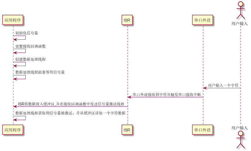
//进行读取, 有数据的话进行回显, 不然进入阻塞
while(rt_device_read(u2_dev, -1, &ch, 1) != 1){
rt_sem_take(u2_sem, RT_WAITING_FOREVER);
}
rt_device_write(u2_dev, -1, &ch, 1);
}
}
int main(void)
{
rt_err_t ret;
//使用默认的配置
struct serial_configure u1_config = RT_SERIAL_CONFIG_DEFAULT;;
//初始化一个信号量, 以及一个处理线程
u2_sem = rt_sem_create("u2_sem", 0, RT_IPC_FLAG_FIFO);
u2_thread = rt_thread_create("u2_deal", u2_deal, RT_NULL, 512, 20, 20);
//开始运行这一个线程
rt_thread_startup(u2_thread);
//寻找使用的USART设备
u2_dev = rt_device_find("uart2");
if(u2_dev == RT_NULL)
{
LOG_E("rt_device_find fail...\n");
return -EINVAL;
}
//配置一下模式
rt_device_control(u2_dev, RT_DEVICE_CTRL_CONFIG, (void *)&u1_config);
//设置一个回调函数
rt_device_set_rx_indicate(u2_dev, rx_callback);
//打开一个USART用的是中断的接收的模式
ret = rt_device_open(u2_dev, RT_DEVICE_OFLAG_RDWR | RT_DEVICE_FLAG_INT_RX);
if(ret<0)
{
LOG_E("rt_device_open fail...\n");
return ret;
}
rt_device_write(u2_dev, 0, "Uart1 config ...\n", rt_strlen("Uart1 config ...\n"));
return 0;
}使用DMA的模式
c
/*
 * STEP 3, if you want using SERIAL DMA, you must open it in the RT-Thread Settings.
 *                 RT-Thread Setting -> Components -> Device Drivers -> Serial Device Drivers -> Enable Serial DMA Mode
 *
 * STEP 4, according to serial port number to define serial port tx/rx DMA function in the board.h file
 *                 such as     #define BSP_UART1_RX_USING_DMA
 *
 */
之后直接关闭, 然后保存就可以了
- 定义一个宏定义