Appearance
I2C
使用流程
- 使用i2c_config_t这一个结构体设置i2c的模式
c
/**
 * @brief I2C initialization parameters
 */
typedef struct{
    i2c_mode_t mode;     /*!< I2C mode */
    int sda_io_num;      /*!< GPIO number for I2C sda signal使用的IO */
    int scl_io_num;      /*!< GPIO number for I2C scl signal */
    bool sda_pullup_en;  /*!< Internal GPIO pull mode for I2C sda signal 是否使用上下拉*/
    bool scl_pullup_en;  /*!< Internal GPIO pull mode for I2C scl signal*/

    union {
        struct {
            uint32_t clk_speed;      /*!< I2C clock frequency for master mode, (no higher than 1MHz for now) 设置时钟的频率*/
        } master;                    /*!< I2C master config */
#if SOC_I2C_SUPPORT_SLAVE
        struct {
            uint8_t addr_10bit_en;   /*!< I2C 10bit address mode enable for slave mode 是不是使用10位地址*/
            uint16_t slave_addr;     /*!< I2C address for slave mode 从机地址*/
            uint32_t maximum_speed;  /*!< I2C expected clock speed from SCL. 最大的时速*/
        } slave;                     /*!< I2C slave config */
#endif // SOC_I2C_SUPPORT_SLAVE
    };
    uint32_t clk_flags;              /*!< Bitwise of ``I2C_SCLK_SRC_FLAG_**FOR_DFS**`` for clk source choice 这一个不用设置 使用默认即可*/
} i2c_config_t;- 初始化给定 I2C 端口的配置, 使用函数
i2c_param_config设置参数 - 进行安装驱动程序
API
i2c_param_config初始化设置
c
esp_err_t i2c_param_config(i2c_port_ti2c_num, consti2c_config_t *i2c_conf)使用I2C编号以及初始化结构体进行初始化这一个I2C设备
i2c_driver_install安装驱动
c
esp_err_t i2c_driver_install(i2c_port_ti2c_num, i2c_mode_tmode, size_t slv_rx_buf_len, size_t slv_tx_buf_len, int intr_alloc_flags)主机发送
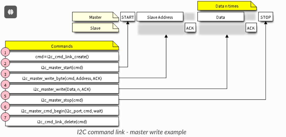
使用
i2c_cmd_link_create()创建一个命令链接。然后,将一系列待发送给从机的数据填充命令链接:
- 启动位 -
i2c_master_start() - 从机地址 -
i2c_master_write_byte()。提供单字节地址作为调用此函数的实参。 - 数据 - 一个或多个字节的数据作为
i2c_master_write()的实参。 - 停止位 -
i2c_master_stop()
函数
i2c_master_write_byte()和i2c_master_write()都有额外的实参,规定主机是否应确认其有无接受到 ACK 位。- 启动位 -
通过调用
i2c_master_cmd_begin()来触发 I2C 控制器执行命令链接。一旦开始执行,就不能再修改命令链接。命令发送后,通过调用
i2c_cmd_link_delete()释放命令链接使用的资源。
前几个函数获取一个发送的命令, 使用i2c_master_cmd_begin实际进行发送
发送的时候需要设置地址
(ESP_SLAVE_ADDR << 1) | I2C_MASTER_WRITE
i2c_master_write_byte(cmd, (ESP_SLAVE_ADDR << 1) | I2C_MASTER_WRITE, ACK_EN);
c
i2c_cmd_handle_t cmd = i2c_cmd_link_create();
i2c_master_start(cmd);
i2c_master_write_byte(cmd, 0x70 << 1 | I2C_MASTER_WRITE, true);//发送一个读地址
i2c_master_write_byte(cmd, 0xEF, true);
i2c_master_write_byte(cmd, 0xC8, true); // 发送一个0xefc8的命令
i2c_master_stop(cmd);
ret = i2c_master_cmd_begin(I2C_MASTER_NUM, cmd, 1000 / portTICK_PERIOD_MS);
if (ret != ESP_OK) {
    goto end;
}
i2c_cmd_link_delete(cmd);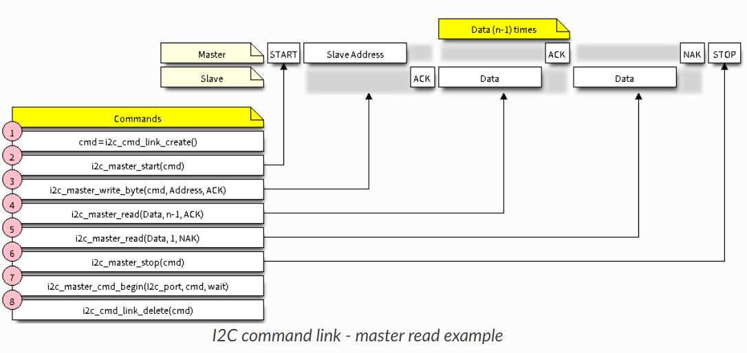
i2c_master_write_byte(cmd, (ESP_SLAVE_ADDR << 1) | I2C_MASTER_READ, ACK_EN);
c
cmd = i2c_cmd_link_create();
i2c_master_start(cmd);
i2c_master_write_byte(cmd, 0x70 << 1 | I2C_MASTER_READ, true);
i2c_master_read(cmd, data, 3, I2C_MASTER_LAST_NACK); //读取三个字节
i2c_master_stop(cmd);

ret = i2c_master_cmd_begin(I2C_MASTER_NUM, cmd, 1000 / portTICK_PERIOD_MS);
i2c_cmd_link_delete(cmd);
从机接收
c
int i2c_slave_read_buffer(i2c_port_t i2c_num, uint8_t *data, size_t max_size, TickType_t ticks_to_wait)阻塞获取数据
从机发送
c
int i2c_slave_write_buffer(i2c_port_ti2c_num, const uint8_t *data, int size, TickType_t ticks_to_wait)这几个数据会进行存储, 主机获取的时候依次发送数据
i2c_master_write_read_device
c
esp_err_t i2c_master_write_read_device(i2c_port_t i2c_num, uint8_t device_address, const uint8_t *write_buffer, size_t write_size, uint8_t *read_buffer, size_t read_size, TickType_t ticks_to_wait)write followed by a read to a device on the I2C bus.
在主机模式下面可以使用这一个函数进行发送一个数据然后读取
- i2c_num -- I2C port number to perform the transfer on 使用的设备
- device_address -- I2C device's 7-bit address 从机地址
- write_buffer -- Bytes to send on the bus 写入的数据(一般是寄存器, 命令之类的)
- write_size -- Size, in bytes, of the write buffer 大小
- read_buffer -- Buffer to store the bytes received on the bus 读取的数据
- read_size -- Size, in bytes, of the read buffer 读取的大小
- ticks_to_wait -- Maximum ticks to wait before issuing a timeout. 等待的时间
ci2c_master_write_read_device(I2C_MASTER_NUM, QMI8658C_SENSOR_ADDR, ®_addr, 1, data, len, I2C_MASTER_TIMEOUT_MS / portTICK_PERIOD_MS); }
i2c_master_read_from_device
c
esp_err_t i2c_master_read_from_device(i2c_port_t i2c_num, uint8_t device_address, uint8_t *read_buffer, size_t read_size, TickType_t ticks_to_wait)一个封装的读取函数
i2c_master_write_to_device
c
esp_err_t i2c_master_write_to_device(i2c_port_t i2c_num, uint8_t device_address, const uint8_t *write_buffer, size_t write_size, TickType_t ticks_to_wait)一个封装的写入函数
示例
使用头文件#include "driver/i2c.h"
c
#ifndef JIAO_I2C_H
#define JIAO_I2C_H


#define I2C_MASTER_SCL_IO           GPIO_NUM_1      /*!< GPIO number used for I2C master clock 两个引脚*/
#define I2C_MASTER_SDA_IO           GPIO_NUM_0      /*!< GPIO number used for I2C master data  */
#define I2C_MASTER_NUM              0               /*!< 使用的I2C序号 I2C master i2c port number, the number of i2c peripheral interfaces available will depend on the chip */
#define I2C_MASTER_FREQ_HZ          400000          /*!< 设置它的速率 I2C master clock frequency */
#define I2C_MASTER_TX_BUF_DISABLE   0               /*!< 主机不使用buf I2C master doesn't need buffer */
#define I2C_MASTER_RX_BUF_DISABLE   0               /*!< I2C master doesn't need buffer */
#define I2C_MASTER_TIMEOUT_MS       1000            //设置超时时间

#endif //JIAO_I2C_H
c
static esp_err_t i2c_master_init(void)
{
    int i2c_master_port = I2C_MASTER_NUM;

    i2c_config_t conf = {
        .mode = I2C_MODE_MASTER,
        .sda_io_num = I2C_MASTER_SDA_IO,
        .scl_io_num = I2C_MASTER_SCL_IO,
        .sda_pullup_en = GPIO_PULLUP_ENABLE,
        .scl_pullup_en = GPIO_PULLUP_ENABLE,
        .master.clk_speed = I2C_MASTER_FREQ_HZ,
    };

    i2c_param_config(i2c_master_port, &conf);

    return i2c_driver_install(i2c_master_port, conf.mode, I2C_MASTER_RX_BUF_DISABLE, I2C_MASTER_TX_BUF_DISABLE, 0);
}
c
// 读取ID
esp_err_t gxhtc3_read_id(void)
{
    esp_err_t ret;
    uint8_t data[3];

    i2c_cmd_handle_t cmd = i2c_cmd_link_create();
    i2c_master_start(cmd);
    i2c_master_write_byte(cmd, 0x70 << 1 | I2C_MASTER_WRITE, true);
    i2c_master_write_byte(cmd, 0xEF, true);
    i2c_master_write_byte(cmd, 0xC8, true);
    i2c_master_stop(cmd);

    ret = i2c_master_cmd_begin(I2C_MASTER_NUM, cmd, 1000 / portTICK_PERIOD_MS);
    if (ret != ESP_OK) {
        goto end;
    }
    cmd = i2c_cmd_link_create();
    i2c_master_start(cmd);
    i2c_master_write_byte(cmd, 0x70 << 1 | I2C_MASTER_READ, true);
    i2c_master_read(cmd, data, 3, I2C_MASTER_LAST_NACK);
    i2c_master_stop(cmd);

    ret = i2c_master_cmd_begin(I2C_MASTER_NUM, cmd, 1000 / portTICK_PERIOD_MS);

    if(data[2]!=gxhtc3_calc_crc(data,2)){
        ret = ESP_FAIL;
    }
end:
    i2c_cmd_link_delete(cmd);

    return ret;
}